Motor Configuration
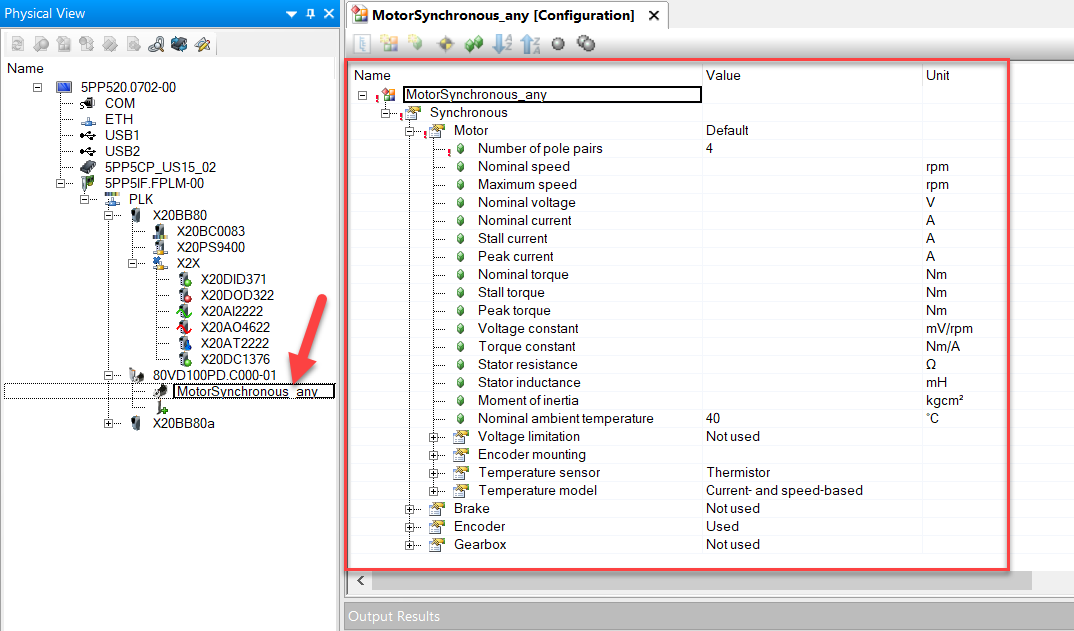
The motor configuration sample provides an example how to change a motor during runtime. If there is no preferred motor during development or the motor parameters are unknown the motor type "MotorSynchronous_any" or "MotorInduction_any" can be used in the hardware tree. After changing the motor parameters the PLC must be reboot for the changes to take affect. The function block MC_BR_ProcessConfig used in this example does not check parameter values for correctness. It is therefore necessary to check the axis for errors after writing new parameters through the PLC logger or the function block MC_ReadAxisError.
|
|
Also see
- Automation Studio help for a description of MC_BR_ProcessConfig (9c2eadae-8494-4e9a-b305-0afa2dabf1d4)
- Automation Studio help for a description of the motor parameters (ce78daa2-e6a6-448c-af72-7b19a7f7ef82)
- Conversion list of synchronous motor parameters
- Conversion list of induction motor parameters using power plate
- Conversion list of induction motor parameters using star equivalent circuit
Repo Link
Here is the link to the repository.
Interface structure
The sample uses a variable structure to communicate with the outside world that can also be used to interact with other tasks. The structure looks as follows:
| Parameter | Function |
|---|---|
| CmdSetMotor | Set the new motor parameters |
| CmdGetMotor | Get the active motor parameters |
| CmdReboot | Reboot PLC |
| MpLink | The axis reference establishes the connection between the function block and an axis |
| ParMotorType | There are two types of possible motor configuration. Use AX_MOTOR_TYPE_SYNCHRONOUS for synchronous motors and AX_MOTOR_TYPE_INDUCTION for induction motors |
| ParMotorSynchronous | Parameters for synchronous motor for set command |
| StaMotorSynchronous | Parameters for synchronous motor for get command |
| ParMotorInduction | Parameters for induction motor for set command |
| StaMotorInduction | Parameters for induction motor for get command |
| StaCompareResult | Shows if parameters in Sta... and Par... are identical |
| ErrId | Error ID |
Program structure
|
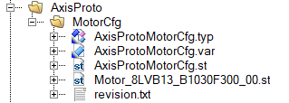
The motor parameter can be outsourced into an extra file with just the motor parameters. This has the advantage that new motors can be added easily without changing any source code in the proto type. |
The program consists of a state machine to execute the commands. The B&R function block that changed the motor configuration needs a name path and not just the MpLink. This name is constructed automatically in the step STATE_MOTOR_CFG_PRE_SET. From this step the state machine goes to the read or write state. The motor parameter can be provided as a separate file and action (see example). It is also possible to set the parameters directly in the structure ParMotorSynchronous or StaMotorInduction.
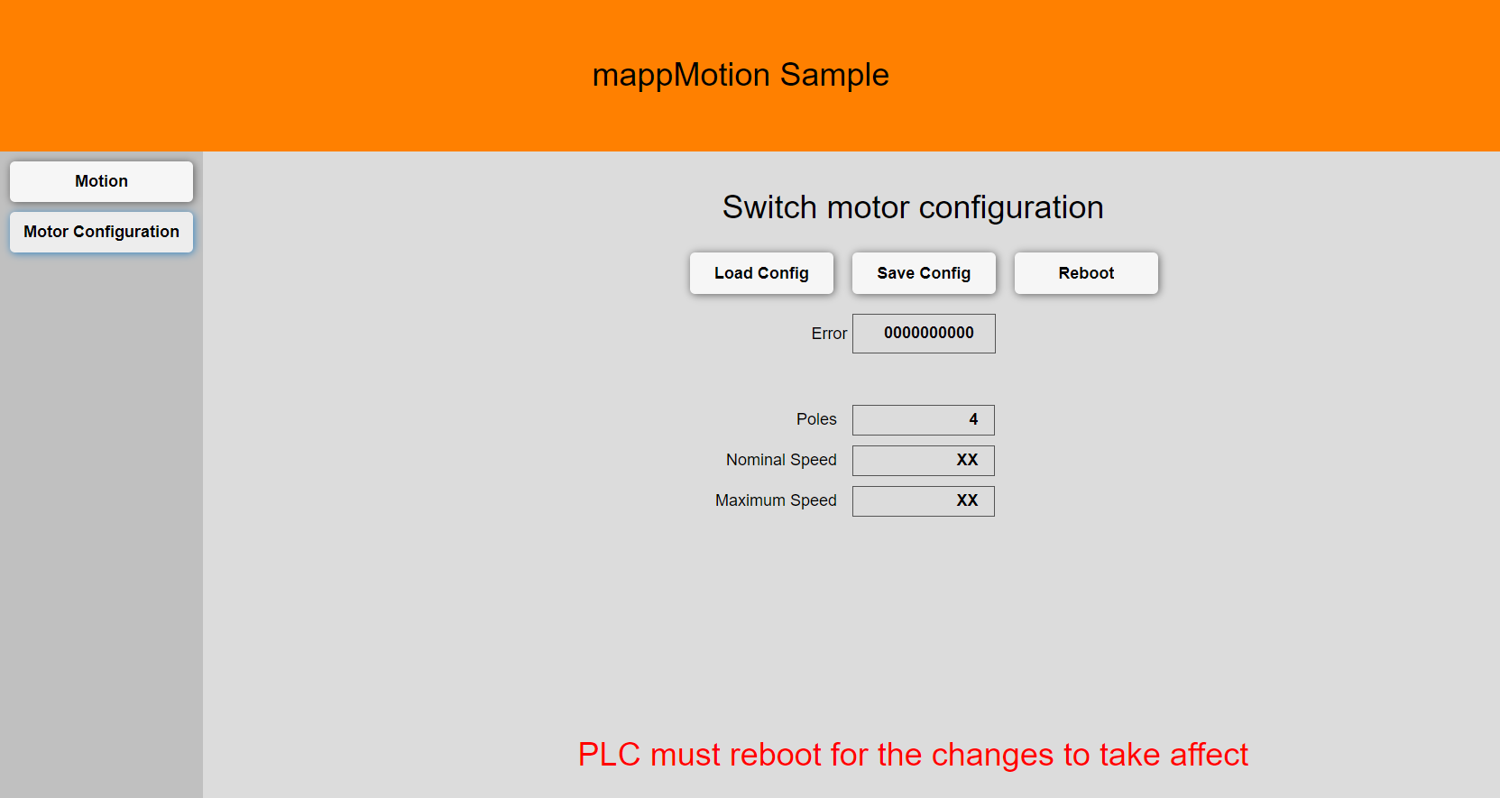
After changing the motor parameters the PLC must be reboot for the changes to take affect.
Sample code
Here is a sample snippet that can be used as a starting point.
Program init
PROGRAM _INIT
    // --------------------------------------------------------------------------
    // Motor configuration
    AxisMotorCfg.MpLink := ADR(gAxis_1);                        // MpLink for axis
    AxisMotorCfg.ParMotorType := AX_MOTOR_TYPE_SYNCHRONOUS;     // Use AX_MOTOR_TYPE_SYNCHRONOUS for synchronous motors and AX_MOTOR_TYPE_INDUCTION for induction motors
    Motor_8LVB13_B1030F300_00;                                  // This action contains the new motor parameters (see additional file with the same name)

END_PROGRAM
Program cyclic
PROGRAM _CYCLIC
    // --------------------------------------------------------------------------
    // Call axis actions used for this drive
    AxisCommonAction;
    MotorCfgAction; // Call motor configuration code

END_PROGRAM
Revision
Version 6 - Update to mapp 5.23
Version 5
- New flag StaCompareResult shows if parameters in Sta... and Par... are identical
Version 4
- Removed dependency from common
- New internal structure
Version 3
- Renamed function block
- Don't read before write
- Minor tweaks
Version 2
- Renamed action
Version 1
- First release